|
It's the Astronomy Online non-Blog, or un-Blog.
Everyone has a blog now and since I am no follower of trends, I decided to merge the blog with the website. And I don't want to neglect the website in favor of posting on the blog.
These are the pages that were on the blog of old:
- Home
- Archive (Index of Pages)
- Me
- Current Trends
- Links
- Soho Live
Links:
Google Maps - Mars
Google Maps - Moon
HiRISE
HiRISE - MRO Imaging
Mac Singularity
Meade4M
Slackerpedia Galactica
Software for the Mac
Starry Night Online
Venus Maps
More Favorites:


Thank you for visiting!
|
|
 |
|
The Project Begins:
The goal of this project is to identify and compare a given list of radio sources to their optical counterpart and image them. Before a target list is given, there are several steps that must first be completed.
Step 1: Location
This is important as the radio sources to identify must be visible from our location, given by latitude. If the wrong location is given, it is likely one of the objects will be below our horizon. Most of the optical counterparts of radio sources visible with a small telescope will reside in our own galaxy, so it is likely the target list will be restricted to the galactic plane. However, there are always exceptions to the rule.
Step 2: Equipment
In order to image these optical counterparts, we will need the proper equipment:
- Telescope of 20 cm aperture or better
- A computer controlled mount for accurate tracking
- A CCD camera to capture the images
- A computer to drive the mount and CCD camera
- Software to control the mount and CCD Camera
- CCD image processing software
I do not own any telescope or camera equipment so I arranged to rent a telescope with access over the Internet. The equipment that I will use:
- A 50.8 cm (20 inch) Ritchey-Chrétien Telescope by RC Optical Systems
- A Bisque Paramount ME computer controlled mount
- An SBIG STL-11000 CCD Camera
While I am renting the equipment to capture the images, I do have (and require) a few additional items:
- An Internet connection
- A computer
- Image processing software (I have CCDSoft 5, Mira Pro, MaxIm DL 4.53, and PhotoShop CS2)
- TheSky Professional (for observation planning)
- Most importantly, purchased time on the remote observatory
The interface for this remote telescope is Browser Astronomy by Software Bisque. It integrates CCDSoft (image processing software) and TheSky (planetarium and telescope control software) – both Bisque products – with their Internet Astronomy Client/Server software.
The equipment is ready to use as focus and image reduction frames are automatically performed and processed for me. According to the telescope owner, one of the design features of the Ritchey-Chrétien is the ability of the telescope to maintain its focus.
Step 3: Equipment Capability
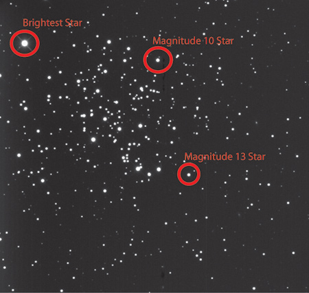
The CCD camera in use for this telescope uses an anti-blooming chip. What this means is that longer exposures are possible without blooming of the chip. This is perfect for image quality but not so good for science. The reason is that photometric measurements will require actual photon counts on the CCD. When an anti-bloom “gate” is on the chip, the pixels can “turn off” to prevent collection of additional photons that might result in the translated electrical signal to spill onto adjacent pixels. In order to determine the viability of this particular CCD camera, a graph must be made that demonstrates its response over time. For this experiment, I captured 18 images of open cluster M67 and measure the response of 3 stars - the magnitudes of the two stars were taken from TheSky 6 Professional:
- The brightest star in the cluster
- A magnitude 10 star
- A magnitude 13 star

The images were captured every 5 seconds, starting at 5 seconds (5, 10, 15, 20……,85, and 90).
Before measuring the pixel value of the images, the images must be reduced – that is corrected for bias, dark frames and flat frames.
The master bias frame, master flat field, and master dark frames are provided by the telescope owner. Using maxim DL version 4.53, I calibrated all 18 images of M67.
Using the Information tool within MaxIm, I collected the values for the 3 stars. These values are the Peak Pixel Count. The maximum number of pixels is about 65,000 so we must determine of this chip will allow the counts to go up that high.
Using Microsoft Excel, I generated three charts:

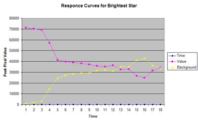
This first chart demonstrates how the chip responds to the brightest star (violet) in reference to the background (yellow). Initially this seems bad, but must be taken into context with the following two charts:

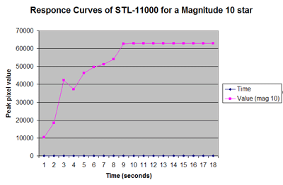
The magnitude 10 star manages to reach its peak relatively quick but does reach the peak value and remain there.

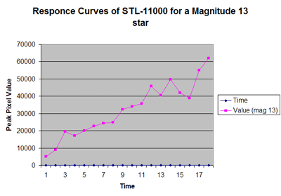
The magnitude 13 star manages to reach its peak on the last image – 90 seconds.
The variations in this (and the other two) graph can be attributed to atmospheric anomalies such as turbulence, water vapor and clouds. These charts demonstrate that faint objects are capable of being photographed while the brightest objects will not over-saturate. It is my opinion that this CCD camera will provide the necessary data to complete this project.
Step 4: The Target List:
Now that I have prepared my equipment and verified the CCD camera’s capabilities, I can now proceed with the project. Many of the targets are sure to be faint - that is at least a magnitude 13. This chip has demonstrated that faint objects can be imaged while controlling the saturation of the brighter objects.
Next Post | Previous Post | Back to Top
|
|

